Smart Mapping ZY3 and ZY4
*******************************************************
New in Scalz 7.1 for Visual CADD Version 7:
*******************************************************
![]()
![]()
These 2 ribalogs are much like the Symbols ribalogs from previous versions but allow for quicker creation of your mapping Markers or Bubbles. All of the Markers shown below were created with just a few clicks, and often just 1 or 2 clicks using these tools.
Below is a complete explanation of the ZY3 ribalog.
Smart Mapping Ribalog ZY3 & ZY4
The Basics
The Smart Mapping Ribalogs are powerful tools for Mapping out your drawings. They are “Smart” because they read your drawings and know what mapping you have done and will tell you if you duplicate a Label Marker or place a Callout or Pointer Marker that does not point to a Label. The ZY3 Ribalog is described below because it was developed first. The ZY4 ribalog has the same basic features, it is a little more user friendly and self explanatory in the way it is designed. The only real feature difference is that the ZY3 ribalog allows for Suffix and Prefix where ZY4 does not. See Fig. 12 below.
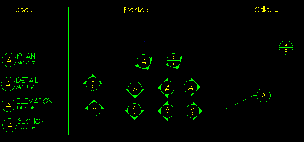
There are 3 types of “Markers” used in Smart Mapping. They are referred to as, Labels, Callouts and Pointers. Notice that a “Label” type Markers can be created in 2 ways, with and without a Symbol associated with it.
Fig. 1 Label Marker with Symbol
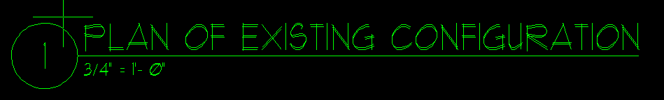
Fig. 2 Label Marker without Symbol

Both of these Label type Markers were created using the Smart mapping Ribalog with just a couple clicks of the mouse. Please note…Only the “1” in Fig. 1 is considered the Label and only the 1/L2 is considered the Label in Fig. 2. The balance of the text is considered a “Prefix” and “Suffix” and is placed on a different layer. A “Prefix” of some sort is required for every Label type Marker. The default Prefixes are “Plan”, “Elevation”, “Section” and “Detail”. These can be changed in the Mapping.ini file if you like. The Suffix is completely customizable for each placement. The “Scale” is optional, and it too is placed on the same layer as the Suffix. The Scale text is customizable in the Mapping.ini file. The Circle in Fig. 1 is a “Symbol” and is optional to a Label type Marker, the layer where the symbol is placed is controlled by your Visual CADD Symbol Settings. The line under the Suffix in Fig. 1 is also optional and placed on the same layer as the Prefix and Suffix. The Label in Fig. 2 is created by “Swapping” the Prefix and Suffix. See the “SwapPrefixSuffix” setting in the Mapping.ini file.
Fig. 3 Callout Marker
Fig. 4 Pointer Markers
Again, all of these Markers were created with just a couple clicks of the mouse.
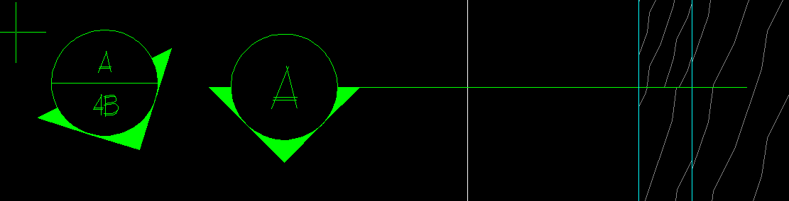
Both Callout and Pointer Markers “point you to”, or “refer you to” a Label Marker. All Markers can have a single line of text or 2 lines of text. When a Callout or Pointer Marker has one line of text, the Marker is referring you to a Label on the current page, and if it has two lines of text, it is referring to a Label on another page. For example, the two line Marker above that reads A/4B tells you to see Label ‘A’ on drawing ‘4B’ to see the view it is pointing to.
Here are some rules about Markers…
1) A Label Marker of the same Number or Letter(s) can only appear on a page once or you will be notified.
2) If a Pointer or Callout refers to a Label that does not exist, you will be notified.
3) You can place as many Callout or Pointer Markers that point to the same Label on any page that you like, you need to police that they are pointing to the correct Label yourself. The tool will only tell you if the Label you are referring to does not exist.
How Smart Mapping works.
All of the “Text” that makeup the Markers is placed on a single Layer that you designate. For this discussion we will use Layer number 0. This layer should not be used for any other drawing objects. If you glance at Fig. 1, only the text “1” in this Label is placed on Layer 0. The rest of the objects (the line, suffix, scale and symbol) is placed on another Layer that you control. All Smart Mapping must be done on this specified layer (0) so you should be sure to set yours to a layer number you will never use for drawing other Visual CADD objects.
This specified Layer (0) is how Smart Mapping Keeps track of your Markers. It simply selects the specified layer and creates a list of all of the text objects found on that layer, it’s actually quite simple.
There are two methods of using Smart Mapping. The method you employ will depend on how you create your drawings. Here are the 2 methods…
1) Method 1…If you are a user that creates many “sheets” (some say “paper spaces”) in the same .vcd file then print different sheets or drawings from one file by selecting them and printing, you will want to use this method known as the “Named View” method. This method requires that you create a “Named View” for each of your the sheets in a set. The “Named Views” must correspond to the name or number of the sheet in the view.
2) Method 2…If you are a user that creates a single sheet or drawing per file and uses a file numbering system to organize your drawings, then this is your method. This method requires that you name your files the same as your drawings.
In method 1, the Smart Mapping Ribalog selects all of the text entities on your Marker Layer (0 as described above) in each named view and creates a list of all of the Markers in your drawing. So, each Marker corresponds to a view or sheet in your drawing. This is how the tool checks your Markers to insure accuracy and do not point to erroneous views or you do not place two Labels of the same name on the same sheet.
In method 2, the Smart Symbol Ribalog has to work a little harder. It has to visit each drawing being worked on and gather the Markers from each file. The tool can be setup to work on all drawings in a folder, or only look in “open” drawings for the Markers for the list and to be checked. It sounds like this could take a lot of time, but you’ll be surprised at how fast it happens. In this method, you can choose to only check the currently open drawings, then just before you print, change the settings so all drawings are checked in a set (open or not) to see if the tool can find any errors for you to repair.
Smart Mapping Ribalog – ZY3

Controls – Brief Description of what each Control does…
Fig. 5

The “Top” and “Bot” (for Bottom) Dropdown Boxes are the heart of the tool. These boxes control the text to be placed in your Markers. The “Top” Dropdown will contain the Text all of the currently place Labels in the sheet selected in the “Bot” Dropdown. The “Bot” Dropdown will contain a list of all of the current “Named Views” in your drawing if you are using Method 1 described above, or if you use Method 2 above, it will contain a list of all of the currently opened files.
You can also type in any values you want in these controls so you can place new Markers at any time.
The “=” button next to the “Top” box allows you to set the text in this box by selecting text in a drawing rather than typing it in. The “=” button next to the “Bot” box allows you to set the text in this box by selecting any “Sheet” if you use Method 1 and File name if you work using Method 2.
Special Feature…If you Right Click on the “v” on the “Bot” Dropdown, the tool will zoom to the current “Sheet” using method 1 and to the Drawing Name using Method 2.
Fig. 6

The Smart Mapping Ribalog can create “sequential” Markers, meaning if you have the “Top” text set at 3 as shown in Fig. 5 and the number in this dropdown set to 1, the first Marker you place will have a “3” in the top text. The next Marker you place will have a “4”, then a “5” and so on. The sequence is reset if you uncheck then recheck the box. If the Dropdown Control has a “2” in it, the first Marker would have a “3” in the top text, than a “5” then a “7”. The sequence works for Alpha character too.
Fig. 7
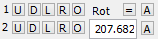
These controls allow you to place Pointer (Fig. 4) and Callout (Fig. 3) type Markers automatically. “U” is for a Pointer type Marker that points “Up”. “D” is for “Down”, “L” for “Left” and “R for “Right”. The “O” buttons place Callout type Markers. The “A” buttons are for angled Pointer type Markers. You set the rotation angle of the angled Pointers in the “Rot” box. The “=” allows you to select a line in V CADD and the angle will automatically be set to point to that line.
The upper set of button create a Markers with one line of text (those that refer to a view on the current sheet) where the bottom set of buttons create Markers with 2 lines of text (those that point to a view on another sheet.
Fig. 8

These are the controls used to create unlimited variations of Label type Markers. The Scale check box controls whether or not a Scale is place with your Label as shown in Fig. 1. The “Label” button starts the Label tool and attaches the Label you as for to your cursor ready for you to place into your drawing.
The eight Scale option buttons allow you to select the scale you want to place for each Label. When you select a sheet or file in the “Bot” Dropdown, the Scale of the current sheet or file is selected automatically. You can change this setting for off Scale views.
The “Plan”, “Elevation”, “Section” and “Detail” option buttons allow you to select the Prefix you want for your Label.
The Auto Edit check box, when checked will select your Prefix text and open the V CADD text edit tool so you can type in any text you want into your label.
The “<T” button attaches the Scale Text onto your cursor ready for you to place into your drawing. The “T>” button attaches the Prefix Text onto your cursor ready for you to place into your drawing.
The Approved button will place the symbol you setup for this button onto your cursor ready for you to place into your drawing.
The Suffix check box controls if the suffix in the Dropdown to its right is added to the Prefix of your Label Text.
The Suffix Drop down allows you to edit a file called “ScalzSuffix.txt”. The contents of this file is listed in the Drip down as shown here…
Fig. 9.
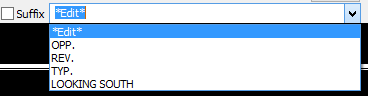
…if you select “*Edit*” the file will be opened for you to edit and make your favorite Suffixes at your fingertips.
Fig. 10
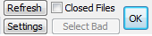
The “Refresh” Button. After editing the “ScalzSuffix.txt”, you will have to click this button to “Refresh” the drop down with your text strings. This button also resets all of the settings in the entire Ribalog including the Marker list. You see, the Smart Mapping ribalog is pretty smart and will try to know when you erase Markers etc. but it may need to be refreshed upon occasion.
The Settings button opens the Mapping.ini file for editing. You Can customize your ribalog to your needs.
The OK button closes the Ribalog.
The “Closed Files” Check Box – For this box we need an example of your file naming convention…Let’s say you number your drawings in this fashion…
Item 1 = File Names = 1.vcd, 1A.vcd
Item 2 = File Names = 2.vcd, 2A.vcd, 2B.vcd, 2C.vcd and 2D.vcd
Item 3 = File Names = 3.vcd, 3A.vcd, 3B.vcd, and 3C.vcd
…and keep them in the same folder, there will be 11 files in the folder, correct? If you have drawing 2A open and this Check Box is un-checked, only drawings 2, 2A, 2B 2C and 2D will be scanned for Smart Markers. If it is checked, all 11 files will be checked for correct markers. Many users leave this box unchecked until they are ready to print an entire set of drawings, then check the box to make sure all drawings are correct.
The “Select Bad” Button – Will select the Text of the Markers that are found to be duplicates or are not pointing to an existing label. Only text in the current drawing is selected.
Controlling how your Markers look
The Label Markers in Fig. 1 and Fig. 2 are quite different. The way they look is controlled by settings in the “Mapping.ini” file found in your Scalz folder. We have provided a button on the Ribalog to open the Mapping.ini file, it’s the one with the “S” on it on the far right end of the ribalog.
Here is a list of the “Settings” controlled in the Mapping.ini file and a description of what each controls.
[Settings]
· MarkerTextLayer – This is the layer index (0-1023) where you want your Markers Placed. Please select a Layer reserved only for these Markers.
· SuffixLayer – This is the layer where the objects (Suffix, the line under the Suffix and Scale) other than the Marker are placed in your drawing. These can be placed on any layer you like.
· UseNamedViews – If you want to use Method 1 above, this should be set to 1 otherwise it should be 0
· Font – This is the font name you want used for your Markers.
· PlaceSymbolsWithLabel – In Fig. 1, the Label has a “Circular” symbol around the text. This setting should be 1 if you want the symbol placed as part of your Label Markers, 0 if you do not as shown in Fig. 2.
· AddSheetNameWithLabel and DividerCharacter – Some users include the sheet name in their Markers as shown in Fig. 2. The “1” is actually the Marker and “L2” is the sheet name. This setting should be 1 to add the sheet name and the “DividerCharacter” setting holds the character place between the Marker and sheet name.
· SwapPrefixSuffix – When this is 0, the Prefix (Plan, Elevation, Section, and Detail) is place before the Suffix See Fig. 1. If this setting is 1, the Prefix is placed after the Suffix and the two are separated by a space character See Fig. 2.
· CheckClosedFiles – When using Method 2 described above, this controls if closed files (in the same folder) are included in the list of Markers to be checked for errors. Use 1 if you want closed files checked and 0 if not. Using Method 1 described above this setting is not used.
· UnderDescriptionLineWeight – This setting controls the line width under the Prefix and Suffix in a Label as shown in Fig. 1. It also controls the line width of the divider line between the upper and lower text in two lined Arrows (See Fig. 4) and Callouts.
· ErrorChecking – You can turn Error Checking off by setting this to 0, otherwise it should be set to 1.
These settings are controlled by controls on the Smart Mapping ribalog…
[Settings]
PlaceScale=1
Increment=1
[Symbols]
TopDefaultText=1
BotDefaultText=1A
Rotation=207.682°
Suffix=' ROOF FRAMING'
Prefix=3
[Text]
Increment=1
Customizing the tool for your use
The following settings allow you to customize the controls on the Smart Mapping ribalog and the way the tool functions for you.
First the “Symbols” section controls the “Path” to the symbols used by the tool. The “PointerSymbol”, “CallOutSymbol” and “LabelSymbol” settings control the name of the 3 types of symbols the tool places. You can use your own symbols if you like. The “Radius” setting is need so the tool knows how long the line separating the upper and lower text in a 2 line Pointer or Callout (See Fig. 4) needs to be drawn. The handle point of your custom symbol must be in the center of the symbol.
[Symbols]
Path=c:\program files (x86)\tritools partners\visual cadd 7\addons\scalz v7\Imperial\Symbols\
PointerSymbol=Arrow
CallOutSymbol=CallOut
LabelSymbol=Label
Radius=0.3125
Next, the “Text” Section allows you to control the line width, type and color of your Markers. It also allows you control the height of the text placed in a 1:1 scaled drawing and a multiplier for the height of the text placed as the Prefix and Suffix in a Label.
[Text]
LineColor=10 (-1 for current Color)
LineType=0 (-1 for current Type)
LineWidth=1 (-1 for current Width)
Height=0.125
HeightMult=2
The following settings control the text on the buttons that create a Rotated Arrow shown here….

[RotatingButtonText]
Top=A
Bottom=A
The following settings control the text displayed on the buttons for placing Pointers and Callouts. The upper row places Markers with single lines of text (thus the “1” to the left and the 2nd row places 2 text line Markers, (thus the “2” to the left) of the buttons. The Right buttons (“O”) place Callout type Markers and the “U”, “D”, “L” and “R” buttons (Up Down, Left and Right) place Pointer type Markers.

[ButtonText]
1Top=U
2Top=D
3Top=L
4Top=R
5Top=O
1Bottom=U
2Bottom=D
3Bottom=L
4Bottom=R
5Bottom=O
The ScaleOptionText section controls the text displayed on the ribalog beside each scale option control. The “ScaleText” section controls what text (Scale) is placed when the corresponding option button is selected. If you want to include either inch (” or double quote) or foot (‘ apostrophe) Markers you must supply a, apostrophe before and after the string of text as shown.
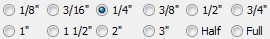
[ScaleOptionText]
1='1/8"'
2='3/16"'
3='1/4"'
4='3/8"'
5='1/2"'
6='3/4"'
7='1"'
8='1 1/2"'
9='2"'
10='3"'
11=Half
12=Full
[ScaleText]
1='1/8" = 1'- 0"'
2='3/16" = 1'- 0"'
3='1/4" = 1'- 0"''
4='3/8" = 1'- 0"'
5='1/2" = 1'- 0"'
6='3/4" = 1'- 0"'
7='1" = 1'- 0"'
8='1 1/2" = 1'- 0"'
9='2" = 1'- 0"'
10='3" = 1'- 0"'
11=HALF SIZE
12=FULL SIZE
The PrefixOptionText section controls the text displayed in the option controls on the ribalog. The PrefixText section controls what text is placed when the corresponding option button is selected.

[PrefixOptionText]
1=Plan
2=Elevation
3=Section
4=Detail
[PrefixText]
1=PLAN
2=ELEVATION
3=SECTION
4=DETAIL
The ribalog has one customizable button for placing any symbol you use regularly. The CustomSymbolButton section controls the text that appears on the Button and the name of the symbol that will be attached to your cursor when the button is clicked.

[CustomSymbolButton]
Text=Approved
Symbol=Approved
There are several Settings you can make to customize your Markers. Here they are with a brief Description…
[Settings]
MarkerTextLayer=0 Sets the Layer for the Text of your Smart Markers (-1 for current Layer)
SuffixLayer=2 Sets the Layer for all other entities (other than text) in your Markers (-1 for current Layer)
Font=Hand Sets the Font for your Markers
PlaceSymbolsWithLabel=1 Controls if a Symbol is placed around your Label Markers See Fig. 1 & 2
AddSheetNameWithLabel=0 See Fig. 2 Adds Sheet Name to Labels when equal to 1
DividerCharacter=/ See Fig. 2 Divider between Label and Sheet name
SwapPrefixSuffix=0 Helps control the look of your Labels
UnderDescriptionLineWeight=1 Set the line weight of all lines drawn (-1 for current Width)
ErrorChecking=1 Turn Off Error Checking when 0
PlaceScale=1 Control if a Scalz is placed with your labels. See Fig. 1 & 2
NumericFileNamesOnly=1 Only files names that start numerically will be checked for Smart Markers
UseTails=1 Tails can be added to your Callout and Pointer Markers See Fig. 11 Below
LabelOffsetX=-0.625 Controls the cursor X offset for your Labels
LabelOffsetY=-0.625 Controls the cursor X offset for your Labels
MakeCursorZero=1 When 1, your cursor will become full screened when placing symbols.
It is returned to normal after placing the symbol. This allows for accuracy of placement.
Fig. 11 - Pointers with "Tails"
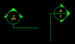
Fig. 12
ZY3 Ribalog – Uses Option Buttons and allows Suffixes
ZY4 Ribalog – Uses Drop Downs for Scales and Labels which adds Flixibility.

Created using Helpmatic Pro HTML